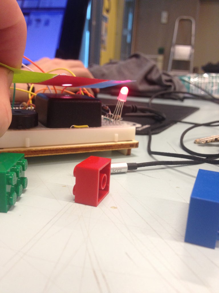
Electronics Projects Circuit Diagram DIY Color Sensor: Arduino-based proof of concept for a simple, DIY color sensor using an RGB LED. It is a two-terminal electronic component that conducts current primarily in one direction. It has low (ideally zero) resistance in one direction, and high (ideally infinite) resistance in the other. Construct the circuit as shown in the
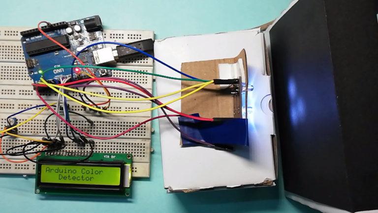
The TCS 3200 Color Sensor comes in the form of a Module with all the components like header pins, 4 White LEDs, Resistors and Capacitors in addition to the Actual TCS 3200 Color Sensor. The following image shows the real time Color Sensor Module. Working of the Project. A simple Color Sensor using Arduino is developed in this project.
Using an RGB LED to Detect Colours Circuit Diagram
For this project, we will use the TCS230 color sensor and the color will be displayed on the ST7735 1.8″ TFT Display. The TCS230 is a programmable color light-to-frequency converter which combines configurable silicon photodiodes and a current-to-frequency converter on a single monolithic CMOS integrated circuit. TCS230 Color Sensor
1 /* This code works with GY-31 TCS3200 TCS230 color sensor module 2 * It select a photodiode set and read its value (Red Set/Blue set/Green set) and displays it on the Serial monitor 3 * and identify if possible the color 4 * Refer to www.surtrtech.com for more details 5 */ 6 7 #define s0 8 //Module pins wiring 8 #define s1 9 9 #define s2 10
Color Detector Using TCS230 Color sensor and Arduino Circuit Diagram
Written instructions for this color detection circuit science project, including a parts list and circuit diagram, are available on the Science Buddies websi
