How a Diode Works Circuit Diagram The maximum power rating P Z of the zener diode is 2W. Using the zener regulator circuit above calculate: a). The maximum current flowing through the zener diode. Diode clipper circuits are also called limiters because they limit or clip-off the positive (or negative) part of an input AC signal. As zener clipper circuits limit or cut-off In the above circuit as you can observe peak voltage of AC signal is V p / -V p and when using a voltage source VCC in the positive clipping circuit, the voltage required for AC signal to force the current through diode will increase from 0.7v to 0.7v + VCC. For example using a 4v source as VCC will clip the positive half cycle at 4.7v voltage

The proper use and connection of a diode are crucial for its right and reliable functionality. Understanding the rating and identifying the polarity is essential for diode proper usage. But the question is how to use a diode properly? It's always recommended to consult the diode's datasheet or seek expert advice when designing circuits Fortunately, there are pre-built diode bridge modules ready to use that already incorporate the necessary diodes and circuit configuration for efficient AC-to-DC conversion. Here you have some examples of diode bridge modules with different packings: Pre-built modules ensure consistent performance, are compact in size, and simplify integration. A diode is reverse biased when it acts as an insulator and is forward biased when it allows current to flow. A diode has two terminals, the anode and the cathode. Uses for diodes include switches, signal modulators, signal mixers, rectifiers, signal limiters, voltage regulators, oscillators, and signal demodulators.
Schottky Diode: A Beginner's Guide Circuit Diagram
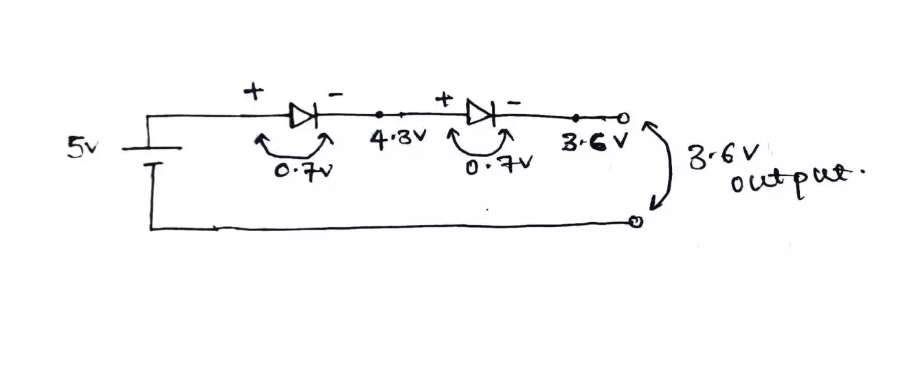
The diodes will also provide a voltage drop into the circuit. For example when I added this diode into a simple LED circuit mounted to a breadboard, I get a voltage drop reading of 0.71V. Why We Use Them. As mentioned we use diodes to control the direction of current flow in a circuit. In the devices you use, full-wave rectifiers are what are most commonly used to convert AC voltage to DC voltage. A full-wave rectifier circuit made with diodes is called a diode bridge. Check out the diode bridge in the circuit below: The diode bridge consists of four diodes - D1, D2, D3, and D4 - that are connected together.

Air Ionizer. The above voltage doubler when extended to many more stages using diodes and capacitors, to form a ladder, it ultimately constitutes a very special device called the air ionizer circuit.. This configuration mainly uses the rectification and blocking feature of the diode, and the charge multiplying feature of the capacitors, to form a high negative voltage generator circuit which
