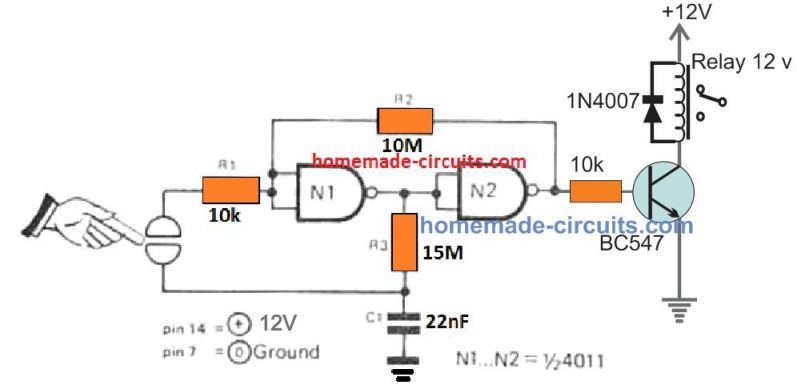
How to make Touch Sensor on Breadboard college projects Latest News Circuit Diagram A switch is the most essential part of any circuit. Different circuits use different switches in them. In this project, we are going to use a Touch Dimmer Switch. This switch is a touch-sensitive sensor that detects the physical touch or proximity. When both the wires are touched, small current flows through the finger and the transistor switches ON, as a result, the load becomes active. Fig. 4 Circuit diagram of touch sensor circuit using BJT Applications of Touch Sensor The capacitive touch sensors can be easily manufactured with an attractive design and in less investment. ions. The first one is a simple touch sensor switch using a single IC 4017, the second one employs a Schmidt trigger IC, the 3rd one work with a flip flop based design and there's another one which uses the IC M668. I have explained the procedures in detail. 1) Using a 4017 IC for the Relay Touch Activation Referring to the below given circuit diagram for the proposed first simple touch

Learn How to make a Touch Switch / Touch Sensor Circuit On Breadboard Tutorial easily step by step with complete instructions, materials and details. Touch s Touch sensor circuit - https://www.build-electronic-circuits You only need 3 components. A transistor, a resistor and an LED. The touch switch is a very simple project based on the application of transistors. The BC547 transistor is used in this project which acts as the touch switch. MAKE SURE TO WATCH THE VIDEO WHICH WILL GIVE YOU THE FULL DETAILS ABOUT THE PROJECT.

How to Design A Touch Dimmer Circuit Using Arduino? Circuit Diagram
This video shows you how to make a simple touch sensor switch on a breadboard using transistors. This circuit can be coupled with a latch and a relay to oper

Many how to make simple touch switch circuit project. To build easy. Using transistor and IC like 555 timer, 4011 CMOS, flip-flop IC.
