Online Circuit Simulator Circuit Diagram Learn how to make simple boost converter circuits using transistors, and IC 555. These step up circuits will convert 1.5 V 3 V to 12 V, 24 V. You can use a 9V 5 amp transformer to build the voltage/current source for the LM317 circuit. You can try the following circuit for the mentioned purpose. Use only 2nos of 2N3055 in the circuit, that
We can therefore construct a circuit that converts a voltage to a current. Looking at the datasheet for the LM324 we can see it's capable of driving 30mA and can therefore be used as the basis of our simple current source without an additional drive transistor. In addition to that we'd like a 0-10V or +/-10V output.

DC Boost Converter (Step Up) : 5 Steps Circuit Diagram
The output voltage from this circuit will range from 7.5V to 35V DC with 60mA Output Current. The AC-AC Converter is quite simple as in comparison to the DC-DC converter . This is because AC-AC Converter only implies a transformer that converts AC from one voltage level to another voltage level.

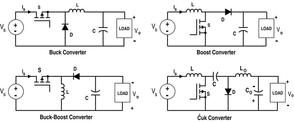
There are many types of voltage-to-current and current-to-voltage converter circuits, and most of them use a combination of opamps and transistors to achieve a high level of accuracy. But when high accuracy isn't necessary, a simple converter of this type can be made using just one or two resistors. A boost converter (step-up converter) is a DC-to-DC power converter that steps up voltage (while stepping down current) from its input (supply) to its output (load). It is a class of switched-mode power supply (SMPS) containing at least two semiconductors (a diode and a transistor) and at least one energy storage element: a capacitor, inductor

How to Build a Boost Converter Circuit: Explained with Calculations Circuit Diagram
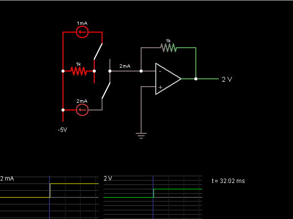
Circuit analysis of Current to voltage converter: The above circuit is a simple current to voltage converter, The non inverting terminal is grounded, and the inverting terminal is connected to a current source. current to voltage converter formula: now see the current flow in the circuit, analyzing the circuit using Kirchhoff's current law.